
Reproduction Parts for 1916-1964 Chevrolet Passenger Cars & 1918-1987 Chevrolet & GMC Trucks SHOP ONLINE | ONLINE CATALOG | ABOUT US

I need to replace the headlight switch in my 36 Master. Is there a video or some instructions on how to do this? I can't figure out where to even start.
Thank you
Ken

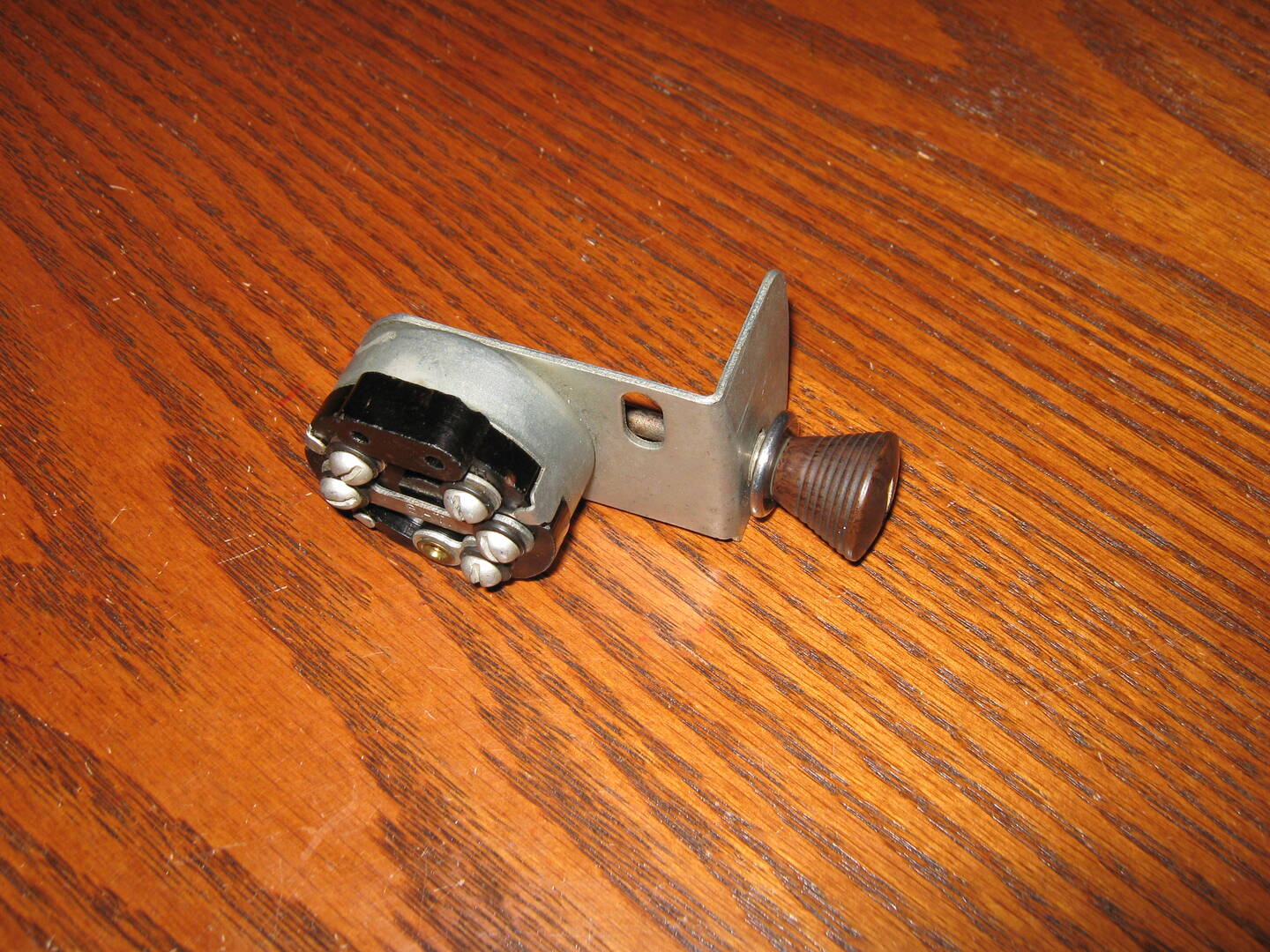
Someone with a 36 will have to verify that this is correct. I 'think' 35-38 are basically the same and I know the 38 so here goes. The chrome bezel that the shaft runs through has a nut on the backside of the dash. It's a 9/16" if memory serves me correctly. Remove that nut. The shaft should be L shaped with the short leg of the L inserted into the switch. It simply pulls out of the switch. Once the nut is off and the shaft loose it's pretty obvious how it comes apart.
7046 old site posts
Save a life, adopt a senior shelter pet
There are many good people. If you can't find one, be one.
1938 Master Business Coupe-Sold, now living in New Jersey
1953 210 Sedan
This is the switch on my old 38. Yours should be similar except for the knob.

7046 old site posts
Save a life, adopt a senior shelter pet
There are many good people. If you can't find one, be one.
1938 Master Business Coupe-Sold, now living in New Jersey
1953 210 Sedan
Thanks Tiny. It looks like I have to take the glovebox box out to get to it. Too many wires in the way.
I got the headlight switch out. There are several on E-bay, some have the resistor and some do not and some just have the boss that the resistor attaches to. My switch does not have the resistor nor the boss. When I was trying to set up my generator a while back, I followed the instructions that Stovbolt gave, but when I turned on the headlights, smoke came out from under the dash and the insulation on one of the wires melted. So, should I have a switch with the resistor? Is my switch bad? It didn't always work, so I'm thinking I need a new one.

I suspect you had a wire connected to the wrong terminal to cause the wire to smoke. A direct to ground is a sure way to get the smoke ions to leave. Trying to put them back is a real problem. If you have any doubt on which wires to attach use a meter to determine if they go to ground (earth elsewhere) or to an accessory, light bulb or other part needing positive electrons to function.
How sweet the roar of a Chevy four
Participant on Chatter since 11/22/2001
19758 posts on the former Chatter site
It dawned on me in the middle of the night that the small, short (3") wire that melted the insulation was probably used as the resistor instead of the actual resistor on the switch. That's easy to replace, but what size is the wire? 14? 16? The headlights worked prior to rebuilding the generator.

Ken, I agree that you may have a wire connected to the wrong terminal on the switch causing the smoke. I may have missed it, but why are you changing the switch? If your existing switch is defective, would be helpful to know what generator is in the car. According to the 1935/1936 Repair Manual, the switch in the Master should have the resistor. This makes the assumption that the original 935-V generator is still in the car and has not been changed to a 943-V. The difference between these two generators is how the field is grounded. The purpose of the resistor is to provide a variable ground path to the 935-V generator field, effectively changing the charging rate depending if the light switch is in the off/parking only or the headlight on position. Said another way, with the light switch off, the generator field is grounded through the resistor (low charging rate) and when the headlights are on, the switch provides a direct to ground path (high charging rate). The 943-V generator field is internally grounded so there is not a separate grounding wire from the generator to the light switch. A wire should not be substituted for the 1 ohm rating of the stock resistor however suitable ceramic replacements are available on Amazon and can be modified to fit a switch with a burned out resistor.
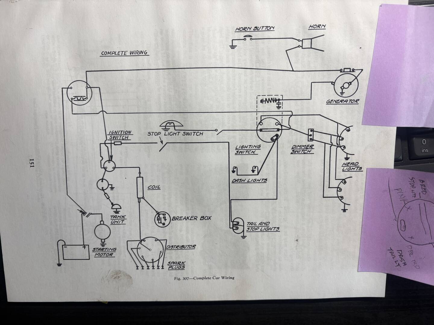
Attached is a photo of the generator circuit showing the resistor from the repair manual. Again, this assumes the car has the original generator.
Hope this helps and is not too much information Mike

OK, now I'm really confused. (Me and electrical are not the best of friends!) It has a 935-V generator. I had it rebuilt, but when I put it in, it was not charging. The repair guy told me that this generator was not internally grounded and I needed to run a wire from the ground stud to a bolt on the generator case. I did that and it started charging. However, it was begging the Amp meter which I thought meant it was over charging. Stovbolt said to run the engine to about 25 mph, I set it at about 1,500 rpm, and with the headlights on move then the third brush until it was charging about 3 amps. I did that, except I forgot to turn the headlights on and when I did, that's when the small wire smoked and melted the insulation. Like I said, my switch does not have any way to mount the resistor. Three of the screws are labeled "R", "H", & "S". Molded into the plastic (?) is "HORN". The melted wire was the screw between R and the 'bar'. The way I read the schematic is that R is the hot wire, S would go to the dash and tail lights. I do not get continuity between these no mater where the switch is aligned, that's why I think I need a new switch. You fellows are much smarter than me on this, so I'll listen to what you have to say.
Thank you very much
Ken


Hi Ken
The way I read your schematic, and the way I read the letters on your switch...
The hot wire from the ammeter goes to one end of the long center bar marked "BAT".
Your dome light wire will attach to the other end of that bar.
The "H" terminal is your head light terminal and the wire going to the headlight dimmer switch attaches there.
The "S" terminal is your parking light terminal and the wire going directly to the parking lights attaches there.
The "R" terminal on the short bar is for the wire to your tail lights, and the wire to your instrument panel lights attaches to the other end of that short bar.
With your switch pulled out to the first notch, you should have continuity from the center "BAT" to both the "R" and the "S" terminals.
With the switch pulled all the way out, you should show continuity from the "BAT" to both the "R" and the "H" terminals.
And of course with the switch pushed in, there should be no continuity between the "BAT" and any of the "R", "S", or "H" terminals.
I should have this written out right, if not, someone please correct me. 🙂
PS
And of course...
Your switch does not appear to have the resister set up for regulating the generator charge rate, so the generator field wire does not go to the switch.
I'm no expert on '36s, but possibly the Master was like that, but the Master Deluxe had the switch with the resistor.
update:
Did a little research and learning
There were only the Master Deluxe and Standard in 1936.
The Standard didn't have the resistor on the switch, but by 1941 only the switch with the resistor was supplied through parts, with instructions that the resistor was simply not used when installed on Standards.
It looks like your car should have had the resistor switch.
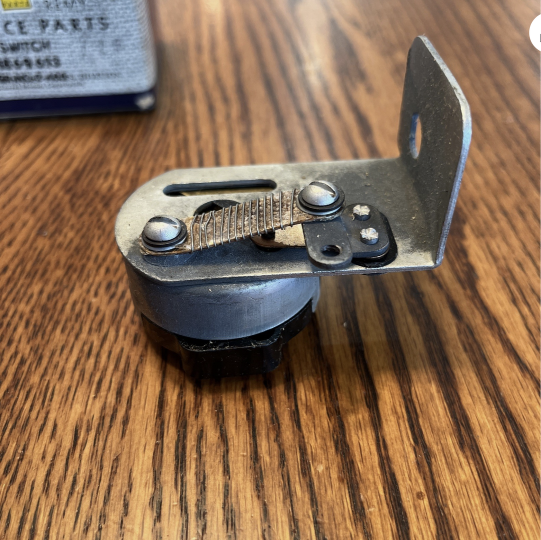
In any case, the resistor appears to have been on the side of the switch opposite the rest of the terminals as in this NOS switch:
https://www.ebay.com/itm/187500990393
Ole S Olson
Saskatoon, Sask, Canada
1946 DR 3/4 ton stake
1139 old site posts
And another picture:

Ole S Olson
Saskatoon, Sask, Canada
1946 DR 3/4 ton stake
1139 old site posts
PS
You had a wire between the center "BAT" bar and the "R" terminal?
Where was your hot wire from the ammeter connected at the time?
If it was connected to that center bar as it should have been, your tail lights would have been on all the time.
As said before, if you smoked a wire, you had a dead short to ground somewhere that you need to find and rectify.
Ole S Olson
Saskatoon, Sask, Canada
1946 DR 3/4 ton stake
1139 old site posts
Sorry if my post confused the topic, i must have missed a previous discussion about having the generator rebuilt and the overcharging issue. In regard to the resistor on the back of light switch, (not in this case) it is easily replaced using these 10 watt, 1 ohm ceramic replacements from Amazon (10 for $6). Much more cost effective than replacing the entire switch. Mike


Actually your post was quite informative.
From your information it looks like Ken has the right generator for a Master Deluxe, but the wrong light switch for some reason.
I'm not sure how that would happen as parts departments substituted the resistor switch for the non-resistor switch by 1941, not the other way around.
Ken has said the switch only worked intermittently.
So, if he can get it apart, clean it up, and get it working, your resistor recommendation and the wire from the generator field terminal to the light switch is all he needs to get the dual charging rate working again.
PS
Wait, maybe not!
The resistor style switch had internal contacts built in that provided a direct ground for the field wire when the lights were on to bypass the resistor.
I'm not seeing a terminal or a way to obtain that with Ken's switch.
PPS
And, Ken's wiring schematic seems to show the resistor part of the switch as being a separate aspect of the switch not connected to any of the other terminals, but activated by the action of the switch never the less.
Ole S Olson
Saskatoon, Sask, Canada
1946 DR 3/4 ton stake
1139 old site posts
Stovblt
So it looks like I should buy a switch with a resistor. But I have another question. Per the shop manual it looks like a wire goes straight from the ground on the generator to the resistor. When I had the generator rebuilt they said it was not internally grounded so I had to run a wire from the ground stud to the generator case. Now, do I run a wire from the generator to the headlight resistor and what about the wire I put on the generator? I'm going to do some re-wiring because whoever did it last changed colors all over and he joints were just wound together and then taped, plus it wasn't wired the way you said. I will replace what I can with some corresponding colors where possible and solder any joints I have to make.
Thanks so much. It has helped a lot.
Ken (bowtiefan)