Yesterday I finally got to dive into getting things configured correctly on my 1940 KC ½ ton pickup.
A previous owner had put the cab on the frame where he found two holes that lined up…but they were the incorrect holes. So cab was located 2” too far forward.
After I figured that out (with the help of 35Mike), I mounted the cab with the correct hardware and am on the path toward getting things assembled in the proper manor.
The radiator brace rod (if that is the correct name for the ‘V” shaped brace) had been installed with the nuts adjusted all the way forward to make the ‘V’ as short as possible, and the fenders and grill shell were barely hung together with a couple bolts, some string and some wire. (It turned out that a lot of what was keeping the truck looking like it should, was the upper radiator hose holding things up!)
I have attached a photo of the truck with the cab in the correct position and it shows that there is something wrong with how the radiator shell is located, in that there are significant gaps between the front of the side of the hood and the grill shell and aft of the side of the hood and the cowl.
The radiator is very loosely bolted to the frame (where it should be, I believe) and I am hoping to find out what the distance should be from the face of the firewall and the rear face of the radiator. With that distance in hand, I should be able to adjust the radiator brace rod to make things line up. (I believe!)
The engine is a 1954 model and the serial number appears to indicate that it was intended for a passenger car with an Powerglide transmission. I seem to remember someone commenting that in some cases there was an issue with water pump/radiator interference with some applications of the newer model engines in the older trucks. Am I facing that? ( I have also attached a photo of the water pump and radiator area.)
(I hope that this is not too wordy, but I am trying to cover most of what I think people would need to know in order to understand the question and perhaps offer a solution.)
Any help is appreciated!
Nick Gurin
Taos, New Mexico
1940 KC 1/2 Ton Pickup
I wont pretend to know much about the 40 models as I have only set up a 38 (similar). Looking at your photos the top of the radiator housing is probably 3" forward of where it needs to be though the radiator itself looks to be in correct position. The front fenders also appear to be forward of their position by the same amount so there may be a link
Tony
Tony,
Thanks for the observation.
I ran out of time the other day when I was working on the truck, but think the next thing I will do is put a framing square against the radiator to see if it is vertical. How close should the fan blades be to the radiator - without being too close?
The fact that the radiator brace rod has so much adjustment available with all those threads makes me wonder if I am not overlooking something. (Then again, I believe the same radiator brace rod part number was used in several years of these trucks, so maybe that is the reason for the adjustability.)
Nick Gurin
Taos, New Mexico
1940 KC 1/2 Ton Pickup
I just used a level to check if the radiator face was vertical, and it is.
Nick Gurin
Taos, New Mexico
1940 KC 1/2 Ton Pickup
I think the radiator is positioned correctly but the support (sometimes called doghouse) maybe leaning forward away from the hood and fenders forward from the running boards.
Tony
Tony,
It appears that the radiator is securely bolted into the "doghouse" and I don't see any opportunities for adjustment in the relationship between those two. (I may be incorrect!) Perhaps the radiator doesn't really care much about being vertical and I should focus on the sheet metal alignment?
I read a Barry Weeks Tech Tip on the Stovebolt forum where he talks about swapping a 235 into these trucks and mentions that the water pump length and the front engine mount can be issues. My level of experience is such that I don't know if these items were already taken care of or not. (I assume that the water pump length issue would show up as interference between the fan blades and the radiator. What issue would the front engine mount cause? - It looks to be securely to the frame and the transmission seems to be correct and properly mounted.)
Perhaps I should ask 2 basic questions:
1. Could someone with a similar truck where things seem to fit together as they should, tell me what the distance is between the firewall and the radiator brace rod mounting holes at the top of the doghouse?
2. Is the water pump pictured above the longer one? (The face of the fan mounting hub is about 4 1/2" from the front face of the head.)
Thanks for giving thought to this!
Nick
Nick Gurin
Taos, New Mexico
1940 KC 1/2 Ton Pickup
I have been told by a Stovebolt.com member that the water pump is the short shaft model.
Nick Gurin
Taos, New Mexico
1940 KC 1/2 Ton Pickup
The different water pump shaft lengths is 1 issue I have heard/seen on here but not experienced myself but there isnt room to change the radiator to that fan as it all sits now, a shorter shaft water pump may help but I doubt enough. You mentioned in another posting that you shifted the cab mounting position I am now wondering if maybe that was in correct move.
Tony
Nick,
It might be an optical illusion, but in your engine photo, it looks like a lot pf space behind your motor. My '39 pickup is apart but I can measure the distance from one of the front bolts to the position of the nut at the back end on the vee bar. It might give you an idea of a starting point. I also just remembered that I have a '39 1-1/2 ton truck in the weeds. Maybe I can get a measurement there for you. You could also send a PM to Mike Rabaut. He responded to one of your posts a while back.
Mike
Many Miles of Happy Motoring
3469 Posts on Old VCCA Chat
Hi Nick
I noticed the same thing Mike did. It LOOKS like you have more space between the engine and cab than there should be.
So, a few questions...
Do your clutch and brake pedals come through the toe board where they should? And are you able to set the pieces with the felt seals in them in around the pedals properly?
Can you set the floor board in and have the gear shift tower on the transmission fit through the hole in the board properly?
If the answers are yes, you will at least have verified that your cab is indeed in the right location on the frame and that the problem lies elsewhere.
Ole S Olson
Saskatoon, Sask, Canada
1946 DR 3/4 ton stake
1139 old site posts
I really appreciate all the folks assisting!
I have taken a number of photos that might assist in determining if the problem is with the location of the cab or not...
1. Front corner of cab on driver's side
2. 3rd cab mount back on driver's side (Note: no hole available forward for this mounting bolt)
3. 4th cab mount back on driver's side (There is a hole forward of this one that a previous owner had bolted the cab through, but none of the other mounting holes then lined up.)
4. Driver's side, rear of head to firewall measurement
5. Rear spark plug to firewall measurement
6. Shows the situation of the pedals against the toe board as they are currently sitting. (The floorboard is home made and shows the difference moving the cab rearward made in the location of the shifter and brake handle.)
I hope that the photos come out in the proper order...
Nick Gurin
Taos, New Mexico
1940 KC 1/2 Ton Pickup
Okay, a few things to state first...
My truck is a '46 3/4 ton with it's original 216 engine.
As far as I know the '40 and '46 cabs were ALMOST the same. But I THINK the firewall was moved forward 1-1/2 inches in 1941 to increase foot room.
And, both '40 1/2 tons and '46 3/4 tons used 36 inch front springs so I assume the rear spring mounts were riveted to the frame in the same place.
Now...
Your 4th cab mount is positioned in the same place as mine relative to the running board mounting rivets, and the 3rd cab mount is in the same place relative to the 3 holes in the frame visible in your picture.
However, the front edge of my cab lines up with the rear rivet on the rear spring mount for the front spring. Yours is about 1-1/2 inch behind that, but that would be right if the firewall was moved forward in 1941 as above.
Therefore...
It looks to me like your cab is indeed mounted in the right place.
The difference in space at the back of the cylinder head MAY be due to the difference between 235's and 216's.
What I don't see in your pictures is the frame around the radiator that the radiator and front sheet metal mounts to, and which is attach to the frame cross member with carriage bolts, pads, springs, nuts and washers.
What is your front sheet metal bolted to?
Ole S Olson
Saskatoon, Sask, Canada
1946 DR 3/4 ton stake
1139 old site posts
Hi Nick
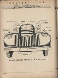
Here is a scan of a page from a Canadian Chevrolet and Maple Leaf Trucks parts catalog.
The radiator support I don't see in your pictures is group number 1.270.
It sits around and slightly ahead of the radiator, and the radiator is bolted to it.
As you can see, the fender supports, the radiator brace rod, and essentially all of the front end sheet metal are also attached to it.
The bottom of the support is attached to the frame cross member with pads, springs, etc as said before.
This illustration is of a 1941-46 style truck, but I believe the '40s were put together the same.
PS
Your rocker arm cover is on backwards.
The oil filler was at the front. 🙂
Ole S Olson
Saskatoon, Sask, Canada
1946 DR 3/4 ton stake
1139 old site posts
There is one more thing though,
I'd swear your gear shift tower was too far forward on the floor.
Is it possible that your engine and transmission are somehow mounted forward of where they should be?
And that that IS the reason for the extra space behind the cylinder head?
Ole S Olson
Saskatoon, Sask, Canada
1946 DR 3/4 ton stake
1139 old site posts
Ole, thanks for asking a lot of questions that might help me get this figured out. Since I don't have enough experience/knowledge to answer most of your concerns directly, I have taken some more photographs that might assist in nailing things down.
Photo #7. Shows the position of the engine mount at the front of the engine that is bolted through the cross member of the frame.
Photo #8. Shows the bell housing mount (over another frame cross member).
Photo #9. Shows a bit of the Radiator Support Frame which rests on a rubber pad and has two bolts going down through the frame cross member.
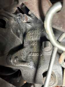
Photo #10. Shows the numbers cast into the side of the transmission in case they assist in describing where the transmission tower should be located.
PS The fix for the rocker arm cover was easy enough...like most everything else on the truck when I received it - it was not bolted down! (Supposedly new (rebuilt?) engine.)
Nick Gurin
Taos, New Mexico
1940 KC 1/2 Ton Pickup


